August 2016
Updated on May 7, 2017 to add roof mounted panel
Many folks have posted about how they installed their solar charging system. This is the way I did it - not wholly original, but there may be something of interest to others.
You can click on any photo for a larger version.
Feel free to skip the narrative unless you are interested in the details.
Introduction
I didn't order my camper with a solar panel system as I both wanted to reduce the purchase price and figured I would mostly only camp in one spot per night. I had them put in wiring to the roof, however, so I could add a panel later. Note, however, I did not use this wiring for this project - maybe later if I add a second panel and place it on the roof.
This year my camping style has shifted somewhat. I'm now more likely to stay in one spot for more than one, or even two days. It was time to add solar charging to my camper.
In reading various posts on Wander the West, I came to the conclusion that a portable, deployable solar panel was a better idea than a fixed panel for me. Yes, one has to store the panel somewhere while traveling and set it up each time one wishes solar power. However, that is outweighed by the advantage of being able to camp in the shade and have the panel out in the sunlight.
I'd read a post or two on WtW where folks had built a solar panel carrier attached to the underside of the camper overhang. That seemed like an efficient way to carry a panel. I had already installed a Rotopax gasoline container carrier in that location, but looking at the measurements of solar panels it looked like there would be space to carry a panel in front of the Rotopax carrier.
I didn't go back and search for posts by others on how they added solar charging or their panel carrier (which I suppose makes this post a bit ironic). As a retired engineer, researching these things for myself is a big part of the fun.
In my research I decided a multi-crystalline silicon solar panel would be the best solution. It's more efficient and smaller than an amorphous silicon panel, and although less efficient than a mono-crystalline panel, it is less affected by partial shade conditions, such as tree leaves, and slightly less expensive.
I knew I'd need a charge controller to sit between the panel and battery bank. The controller regulates the voltage from the panel and also insures the batteries are not overcharged. There are various technologies to accomplish this function. A PWM (pulse-width modulated) type controller would be a good fit in the power range I would be installing and less expensive than the MPPT type, which is better for higher power applications.
In looking at various panels and controllers, sold both individually and as kits. I decided upon a 100W kit from Windy Nation. Besides the multi-crystalline panel, the kit included a PWM charge controller that could handle up to four 100W panels - so if I wanted to add capacity later, I would not have to get a new controller. There is an LCD display on the controller where one can monitor charge voltage, current, etc. The controller also included a temperature compensation sensor & circuitry. This adjusts the charge voltage thresholds depending upon the temperature of the battery, which is recommended by the battery manufacturer. The kit also included wire & connectors to connect the panel to the controller. It included mounting brackets which I would not need. The kit, with shipping, was $185.
I've included a parts list at the end of the post. Most parts were purchased from Amazon and you should be able to find them there. Fasteners were purchased locally. Other items as noted.
Take heart that I won't include a step by step description of my installation. I will include a few notes and I will be glad to answer any questions you wish to include in the comments or in an email.
 |
| Charge Controller mounted on forward wall of camper |
Panel and wiring
 |
| Close-up view of controller and wiring. Black wire on top leads to battery temperture sensor. |
I wired the controller, panel, and batteries as instructed in the kit documentation. I used fuse holders to protect the wiring from the panel and battery bank as recommended in the kit instructions.
 |
| Battery compartment showing the two AGM batteries, ammeter shunt, temp. sensor, and wiring |
As an aside, the LED ceiling lights in my camper always flickered when the water pump ran. This was most irritating and noticeable at low flow rates at night. The manufacturer never figured out how to fix this. It was suggested to me by Bill Harr, who built out his own camper from a shell, to run separate wiring from the battery to the pump. I ran a fused line from the battery positive terminal to the water pump switch in the original monitor panel, and a separate line from battery minus to the water pump. This eliminated all flickering in the LED lights. This circuit is not controlled by the master on/off switch of the camper, however, as the water pump has it's own switch (and is fused), I don't see this as an issue. Note that by wiring the pump this way, its operating current does not go through the shunt and is not monitored by the ammeter.
I mounted the Zamp connector, which includes a snap-on cover, under the front camper edge where it extends just over the sides of the truck bed. This will connect the panel wiring to the charge controller. I had to drill through the plywood and carpet. The wood split a bit which is why the black silicone sealant is smeared all around.
 |
| This is where the wiring from the solar panel connects to the charge controller wiring. The gizmo at the top of the photo is one of the LED downlights. |
I purchased a digital panel meter that displays Vdc, Amps, Watts, and Energy (Wh). This is not necessary but informative. I wired it as per its instructions. The model I chose came with a 50A shunt which I installed between the battery bank negative and the camper ground. That way it monitors all the load current though the batteries. As of this writing I have only temporarily mounted it (see photo). I intend to cut a hole above the original battery/water monitor panel, and below the 12Vdc outlets, and install it in that location.
 |
| Digital panel meter near location to be installed permanently |
Carrier
I ordered two pieces of aluminum C-channel from onlinemetals.com, as I didn't find any channel of appropriate dimensions locally. The 48" lengths would extend about 4" beyond the panel on each side. In retrospect cutting them a bit shorter would have been better as the panel tended to slide from side to side between the padlocks (see next paragraph.) I later cut pieces of plastic and drilled them for the padlock shackles to remove the slack (sorry, no photo).
 |
| C-channel with bolt "stud", plastic strips, and padlock hole |
To mount the C-channel under the camper I first drilled and tapped holes for the bolts. This allowed the bolts to act as studs. It is important to select the bolt length so it doesn't stick above the surface of the bed platform. I drilled holes in the channel sides near the ends that would allow me to add padlocks once the panel was in the carrier. These would make it harder for someone to steal the panel and prevent it from sliding out.
I used contact cement to hold plastic strips on the side and "bottom" of the channel to allow the panel to slide more easily and prevent metal on metal contact. See the photos. The plastic strips were left over from the installation of replacement windows in my house. There might be something similar at your home improvement store.
I then drilled and counter-sunk holes from inside the camper, under the mattress. I could then push the "studs" up into these holes and screw on the nuts from the inside. This worked in theory much better than in practice. It was difficult to get the holes in exactly the right places, so I had to widen the holes more than I would have liked to get the channel to fit flush with the camper. This technique did have the advantage that I could install the carrier "mid season" without removing it from the truck.
I spaced the channels based upon the width of the solar panel, plus about half an inch. In reality it worked out to be slightly more than this, but the space is needed to more easily allow the panel to slide into the channel without binding.
I used silicone calk on the top surface of the channels and especially around the base of the "studs" to seal the holes into the camper. Inside the camper I squirted E6000 glue in the holes especially those holes that had been enlarged to fit the bolts. This was to help strengthen the attachment of the bolts to the camper.
 |
| Carrier mounted under camper above the truck cab |
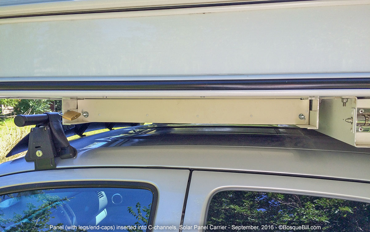 |
| Panel, with end-caps, in the carrier. You can just barely see the front bit of the Rotopax carrier. |
The panel slides into the channels with the tempered glass side down. The resulting cavity conveniently holds the panel electrical cabling. I fold the cables in a cheap plastic tarp to keep them from rattling.
 |
| Close-up view of panel, with end-caps, and padlock |
I purchased 22 feet of vinyl coated wire rope and crimped small loops in each end. I taped this to the solar panel cable. When I deploy the panel I padlock one end of the wire rope to one of the holes in my camper lifting jack brackets and the other to a hole in the solar panel frame. That won't stop a determined thief, but will hopefully discourage casual pilferage.
Panel legs
 |
| Solar Panel deployed with legs set for optimum sun angle. Note also wire rope taped to electrical cable. |
I used 1" x 2" lumber I had in the garage to fashion legs. The legs were cut the length of the short side of the solar panel (see next paragraph). I drilled the panel flange and the legs for a 1/4-20 bolt, washer and wing-nut. This would allow the panel to be set at any angle to face the sun the most directly.
To close off the ends of the carrier, to make end-caps if you will. I bought pieces of white vinyl wall cove base at Home Depot. I trimmed the vinyl to fit between the channels and the underside of the camper overhang. Note I had to cut the vinyl wall cove to be longer than the legs if I wanted to close off the cavity, as the channels were farther apart than the panel width/leg length (see the previous section). This seems to work fine, but I wonder if it would have been better to cut the legs to fit the distance between the channels (minus a bit for clearance) instead.
I used E6000 adhesive to glue pieces of vinyl wall cove base to the outside of the legs. Once the glue cured, I drilled and inserted (previously painted) round-head wood screws to insure the vinyl would not come loose.
I then painted the wood legs with the white spray paint that I'd used to paint the wood screws. This would provide some weather protection and make the finished assembly look a little nicer. The vinyl is thick enough to be fairly stiff. It deforms enough to fit over the bolt heads as the panel slides in, but stands straight enough to close off the cavity against wind or rain.
Note that during my first trip with the panel in the carrier, the panel bounced up & down slightly when on rough roads. This not only made a racket, but I felt it might damage the panel if the impacts were too strenuous. I tried various shims on the road to minimize the problem. I thought about it for the remainder of that trip and came up with a solution. I drilled holes in the legs and panel at the opposite end from the hinge bolts. I inserted another set of 1/4-20 bolts and wing-nuts. This held the legs firmly against the solar panel and the stiffness of the vinyl wall cove held the panel firmly enough against the bottom of the channel that on my next trip out I had no issue with banging or rattling of the panel even on rough roads without shims or pads.
Conclusion
The system works great. In full sun the 100 watt panel/charger pumps between 5 and 6 amps into the battery bank. The output drops a surprising amount with even thin high clouds, but not much one can do about that. FYI, the refrigerator draws about 4.5 amps when the compressor running.
The carrier also works very well. It does require lifting the panel horizontally and sliding it into the channels. The extra space between the channels allows it to slide in easily without binding, especially if the panel is slightly misaligned when inserted. The second set of fasteners on the legs keep the legs in position while lifting and sliding, and prevent the panel from bouncing on a bumpy road in conjunction with the vinyl wall cove end caps.
Parts List
Panel, Controller, and electrical
WindyNation 100 Watt Solar Panel Off-Grid RV Boat Kit with LCD PWM Charge Controller + Solar Cable + MC4 Connectors + Mounting Brackets
DROK Digital Multimeter (panel mount) with 50 Amp shunt
Zamp Solar RV RVROOFSIDE Sidewall Port
CES 2 Pin Quick Disconnect Harness SAE Connector Bullet Lead Cable
Sea Dog Watertight Inline Fuse Holder, 30A, 10AWG
Scotty Marine In-line 30 Amp Fuse Holder
10AWG and 12AWG copper stranded wire
crimp butt-splice connectors
Legs
1" x 2" pine for legs
White 4" x 48" x 0.080" Vinyl Wall Cove Base (Home Depot)
1/4-20 Hex Head Bolts
1/4-20 Wing Nuts
small round-head wood screws
contact cement
white spray paint
E6000 adhesive
Carrier
2x 48" length Aluminum 6063-T52 Bare Extruded Channel Architectural, 3" x 1" x 0.125"
1/4-20 Hex Head Bolts
1/4-20 nuts
plastic strips
silicone sealer
Security
3/32 in Vinyl-Coated Wire Rope (Home Depot)
2x Cable Ferrules (to make a loop at each end of cable)
2x small padlocks with common key
Tools needed
Power drill and bits
1/4-20 metal tap
crimp tool for electrical butt splices
crimp tool for wire rope ferrules (Home Depot let me use theirs in the store when I purchased the wire rope and ferrules)
wood saw
Update - May 8, 2017
Adding a 100 Watt Solar Panel to the Camper Roof
The first night of my recent White Rim Trail trip a strong, gusty wind came up in the middle of the night. I'd left my deployable solar panel set up and "cleverly" aimed it where the sun would rise in the morning. As I listened to the wind, I thought that my panel might be vulnerable, but by the time my sleepy brain came to that realization, I figured it was already too late. In the morning, sure enough the panel was face down. That might not have been too bad, except it landed on the only sharp pointy rock for yards around. The tempered glass was totally shattered, but stayed in place as the solar cells are attached to the glass by a clear film. I was to learn later that the panel still worked, though its out put was less than a third of normal.
The other campers on the trip had solar panels on their roofs. This lead me to rethink my goals. I do like having a deployable panel if I park in the shade, but it is one more thing to do when I set up camp, and then to store before leaving. Plus, if I don't drive enough to have the truck charge the batteries and park at a trailhead during the day, or if I am parked along the road near a fishing spot, I would be reluctant to deploy the panel for a possibly short amount of time.
Seemed like adding a roof mounted panel would give me the best of both worlds. I had already wired the solar panel charge controller and it was designed to be able to handle up to four 100W panels. The roof mount electrical connector was already in place, too. So, when I returned home I ordered two of the same brand 100W panels - one to replace the deployable panel, the other to mount on the roof.
I did not want to drill holes in the roof. First, they might leak; second, there is the issue of figuring out where to drill and get a good mounting point. I researched on the web and also discussion topics on the Wander the West forums. 3M VHB mounting tape sounded like an ideal solution. I saw where AMSolar in Oregon used a 1"x2" piece on each of the four mounting brackets on their RV roof mounts and even watched one of their videos showing how they do it.
I purchased 5 pieces of 1"x4" 3M VHB tape via Amazon to use on 4 brackets I would make myself. This would be double the amount really needed, but would comfort me that it would really, really hold.
 |
| Completed solar panel roof mount. See procedure text below. |
Procedure
I bought a piece of 1-1/2" aluminum angle at the hardware store and cut four 4" lengths to use as my brackets.
I drilled a clearance hole for a #10 sheet metal screw in each and figured out where to drill on the side of the solar panel aluminum frame. I wanted 3/4" to 1" clearance between the bottom of the frame and the roof to allow a bit of air cooling for the panel. By mounting into the side of the frame, I could replace the panel if necessary without disturbing the (hopefully) permanent bond of the bracket to roof.
I cleaned & prepped the bottom of each bracket and applied a strip of the VHB tape to each (keeping the backing on the outside of the tape.
I cut off the leads from my damaged panel and soldered the bare ends to the end of the CES 2 SAE cable that I had left over from the previous project, that fit the pre-installed roof connector. I then plugged this into the leads from the new panel and dressed the wiring.
I attached the brackets to the panel frame using #10 3/4" stainless steel sheet metal screws and ss lock washers. I lifted it onto the camper roof, positioning it where I thought best, 4" in front of the vent and centered side-to-side. This would place it over the existing panel wiring plug, too.
I marked where the brackets would attach and moved the panel out of the way. I'd previously power washed the roof. I then scrubbed the attachment points with abrasive sink cleaner, rinsed well, sanded lightly with fine sandpaper, and rinsed again, then wiped the attachment area with a clean cloth and rubbing alcohol.
I positioned the panel in place and slightly loosened all screws. Using gaffer tape I held down the two brackets on one side. I lifted the other side, propped it up a couple inches and peeled the backing tape off the VHB tape on the bottom of the two brackets. I removed the prop and carefully lowered the panel making sure the bottom of the brackets were parallel with the roof. I pressed down hard for a few moments.
I repeated the procedure on the other side, except I first plugged in the electrical connection and ran a little silicone caulk around it to keep out water.
I checked that all brackets were flush to the roof and tightened the screws.
After a couple of days I caulked around the bottom of the brackets. Since the tape was only 1" wide and the brackets were 1-1/2" wide, I didn't want water to get into that gap, freeze, and lift the bracket.
I think this just about covers it. Everything seems to be working well. Let me know if you have any questions.
Thanks for reading.